Schematic Circuit Diagram Using 7493
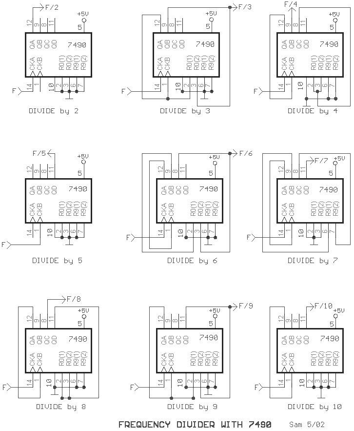
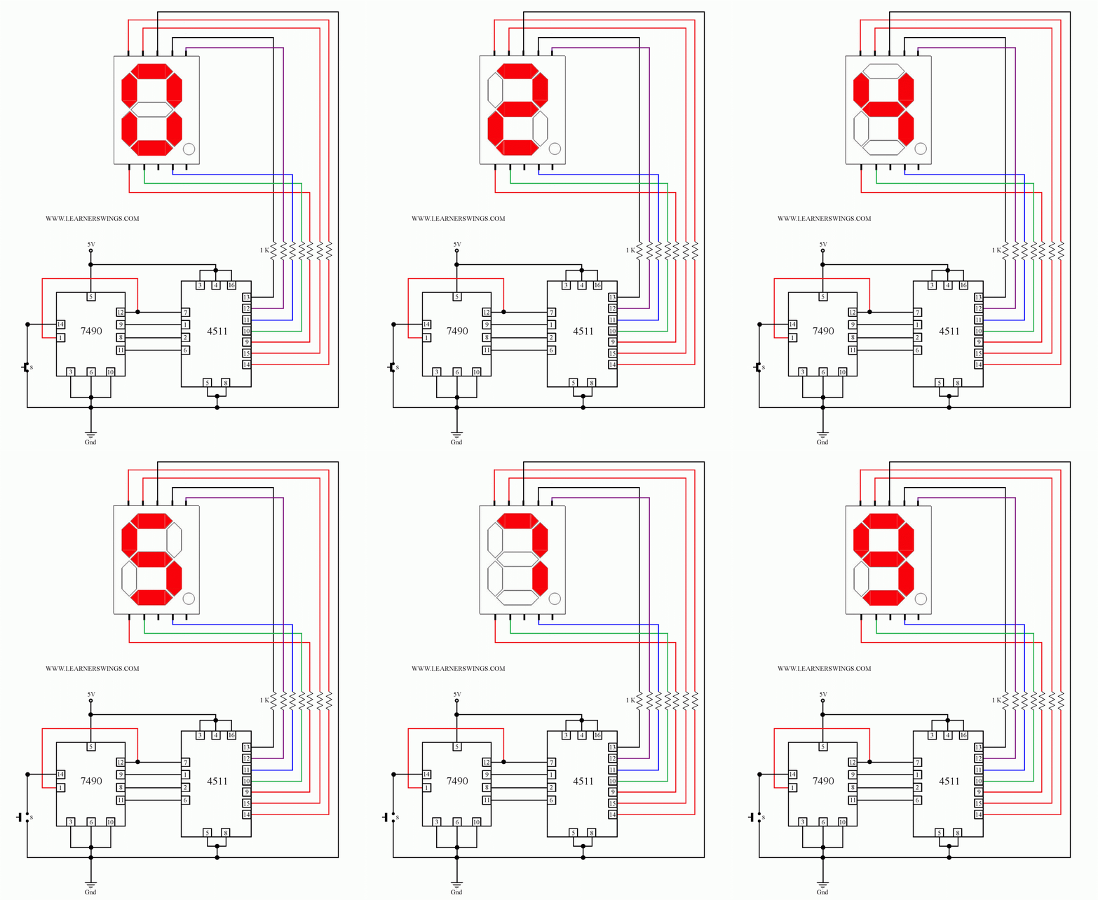
Circuit to control a seven segment display by 7490, 4511 and a press Divider 7490 frequency circuit diagram ic circuits 74ls90 digital clock divide counter based source decade gr next binary desolator build Counter mod 7493 ic using
14+ Ic 7490 Pin Diagram | Robhosking Diagram
555 timer diagram block circuit chip does ne555 datasheet inside pinout work works eleccircuit look function Mod 14 counter using ic 7493 Solved the circuit diagram is given for a 7493 counter ic.
How does ne555 timer circuit work
Datasheet pdf ti acquired instruments 23rd texas september binary decade counters datasheetbankCounter ics 14+ ic 7490 pin diagramIc segment circuit datasheet seven diagram timer cathode 555 common 7490 4511 display control button switch using arduino press counter.
0 to 99 counter circuit using 555 timer and cd4033 ic » counter circuits7493 counter ic diagram circuit given mod connections necessary external make solved including vcc transcribed text show problem been has 7493 ics circuits sanfoundryIc circuits opamp.


14+ Ic 7490 Pin Diagram | Robhosking Diagram

Solved The circuit diagram is given for a 7493 counter IC. | Chegg.com

Counter ICs - Digital Circuits Questions and Answers - Sanfoundry

Circuit to Control a Seven Segment Display by 7490, 4511 and a Press

MOD 14 Counter using IC 7493 - YouTube

0 to 99 Counter Circuit using 555 Timer and CD4033 IC » Counter Circuits
7493 PDF - Decade and Binary Counters - TI - DataSheetGo.com